Real-time Prior-Map based Localisation and Navigation of Autonomous Ground Vehicle in GPS-Denied Environment
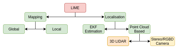
Localisation In Mapped Environment [ LIME ]
Introduction
Wheel odometry based localisation is very inaccurate. However, it can be corrected using Prior Map matching based approach. Prior Map matching based approach alone are computationally very expensive, thus using it to correct parameters of approximate localisation makes the process both efficient and accurate.
3D Point cloud Map is divided saved as multiple small blocks, and neighbor blocks are imported using approximated localization information using wheel and inertial odometry, to save memory and computational budget. The 3D Point Cloud is simultaneously processed to extract essential features information and 2D Lane Grid Map. The 2D Lane Grid Map is used for Navigation and approximate localisation using Robot Localization package, while ICP based methods are used to correct the localization using the essential feature point cloud data. Time delayed computation model is being used to correct the present state localization by making correction to the previous state information, making the process Real-Time.
Report - Index
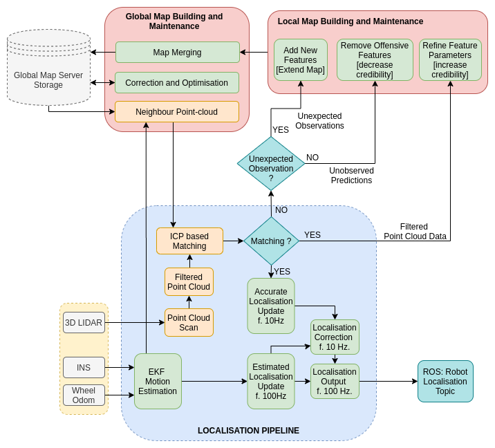
Pipeline Workflow
Mapping Environment: Creating Dataset of IIT Kharagpur
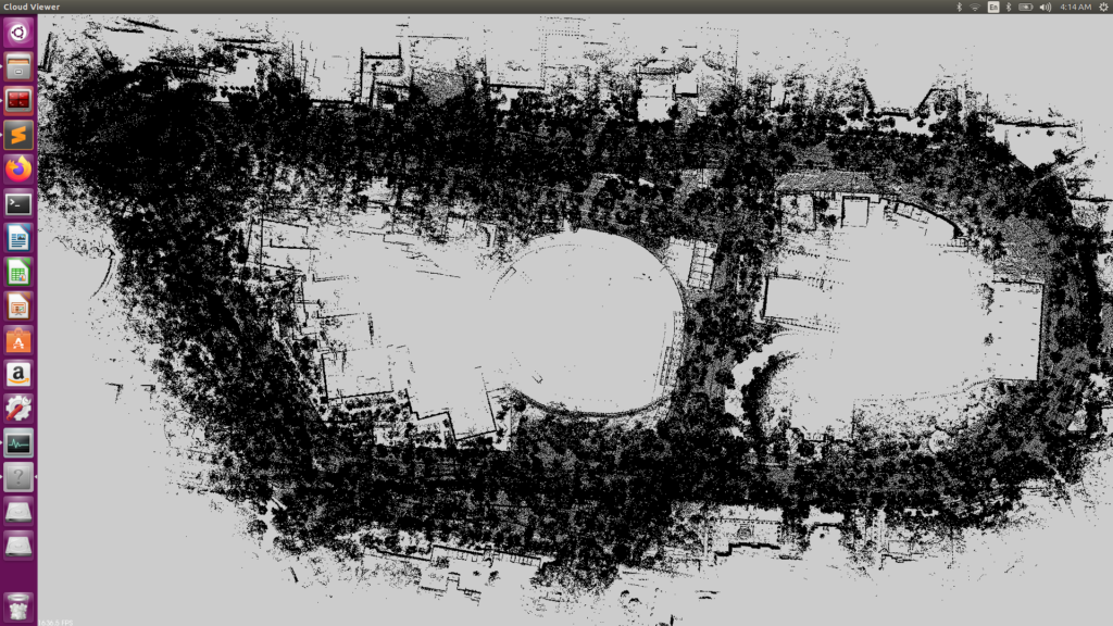
Map Merging: Global Map
3D Point Cloud to 2D Lanes Grid Map
Edge Extraction on Unorganized 3D Point Cloud
Dividing and Importing 3D Point Cloud Map in Grids
Localization approximation using Odometry
Real-time Correction using time-delayed ICP based method
Due to Cloud Storage limitations, the Dataset is not available online yet. If required for research purpose, one can drop me a mail at rishabh.17iitkgp (at) gmail (.) com
Map Merging: Global Map
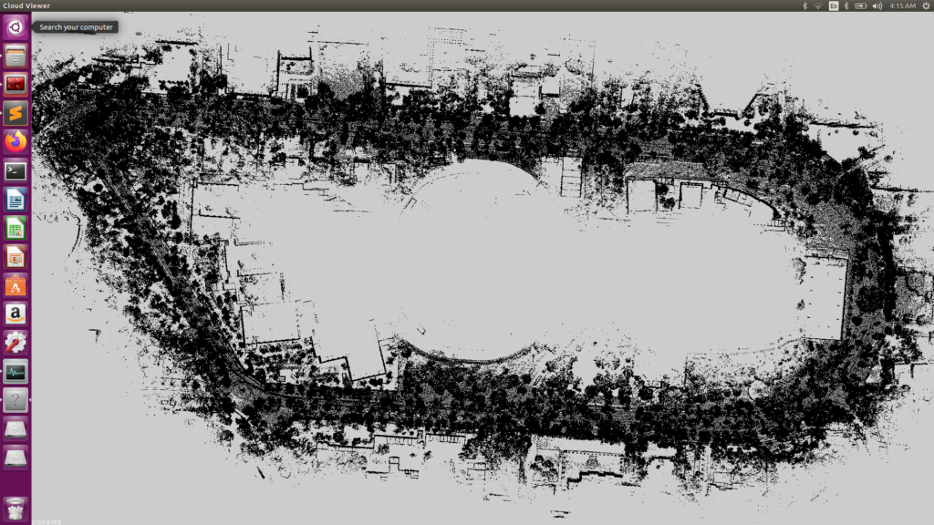
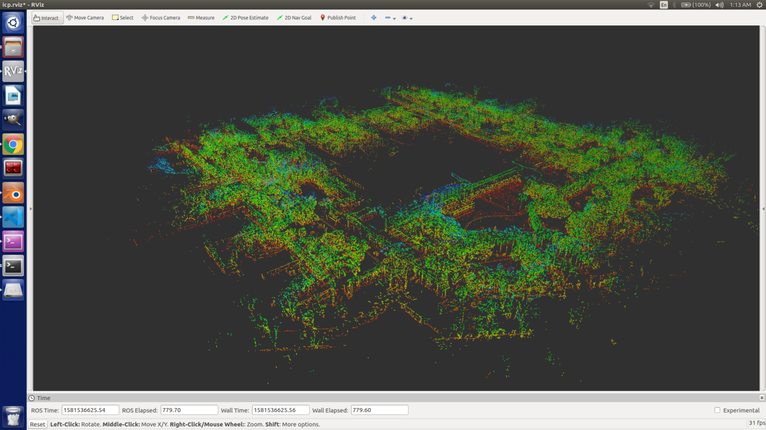
Method 1: ICP Based Map Merging [Naive and Inaccurate]
Map Data from different vehicles recorded at different time, can be merged to create a global map. This above shown map is highly inaccurate at it was made using ICP method at 0.8 matching ratio. We are working on improving this performance by using GPS coordinate to provide initial estimate for map merging.
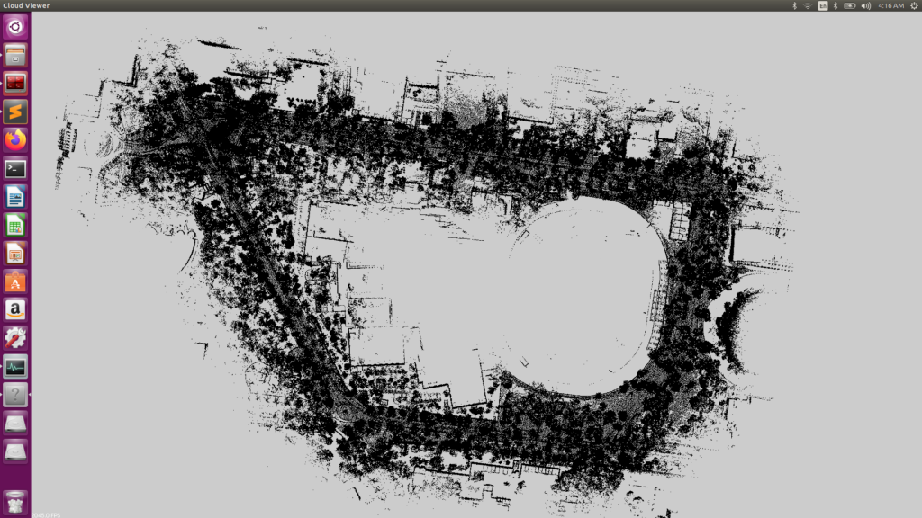
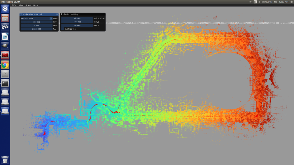
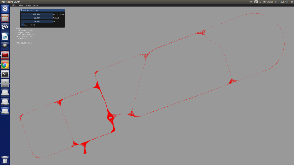
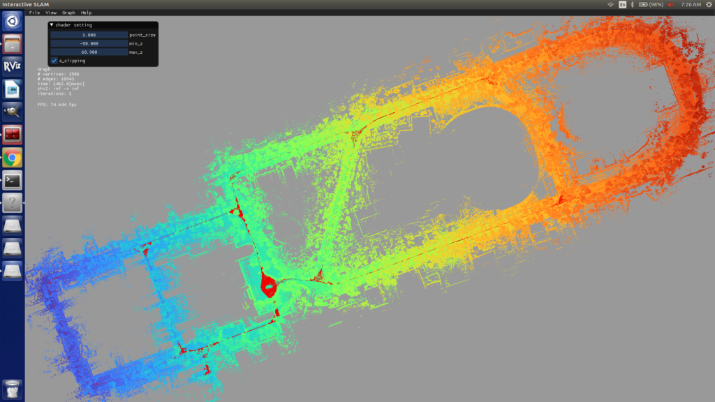
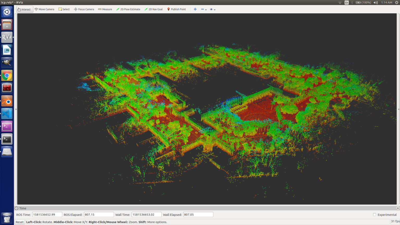
Method 2: Lego LOAM and Interactive SLAM [Accurate and Efficient]
Problem: As ICP treats every single map as a rigid entity, even slight loop closure errors duringn individual mapping could result in maps that are impossible to merge without glaring inaccuracies. Also, just using ICP to merge maps does not improve the accuracy of the common regions.
Solution: Using graph optimisation with dense loop closures solves this issue gracefully. After manually defining only one initial edge per map (which uses GICP between two LiDAR scans, one from each map to be merged), using graph optimisation already leads to better results than ICP. But the real advantage of using this method is that maps aren’t treated as non-deformable, rigid entities. Instead of using the final pointcloud for each map, dense loop closures are done between component LiDAR scans using GICP. This method optimises the entire graph as a whole, leading to highly accurate maps. Also, regions which get mapped multiple times gain accuracy due to dense loop closures.
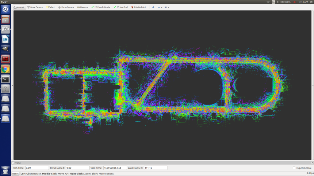
Merged Map Superimposed on Ground Truth Image Top View
Next Step is to Automate this process using Keypoints Features in Map and their estimated coordinate to identify loop closures. [Chicken and Egg all over again!]
2D Lane Grid Map Extration from 3D Point Cloud
Pipeline to extract 2D Lane Grid Map from 3D Point Cloud and saving it as laser_scan data for the Robot_localisation package. This is used for Navigation of the Autonomous Ground Vehicle, and also estimate localization using Odometry data. Dataset: KITTI P.S. : The huge error in localization of the vehicle after the turn is due to missing Wheel Odometry information in KITTI Dataset. [KITTI dataset does not contain wheel odometry data]. The implementation on our own dataset will be updated soon!
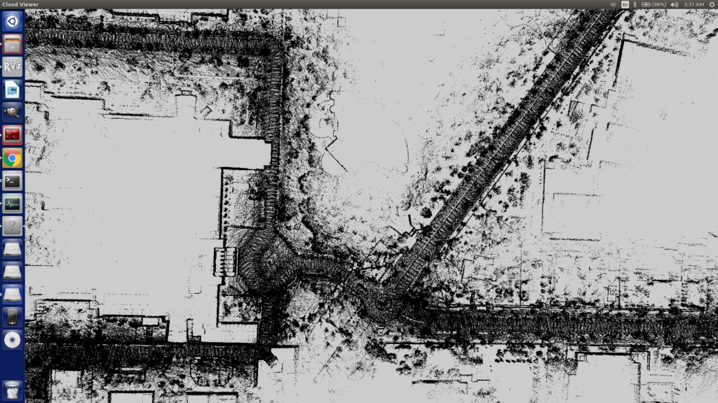
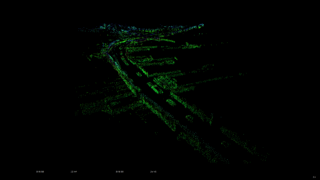
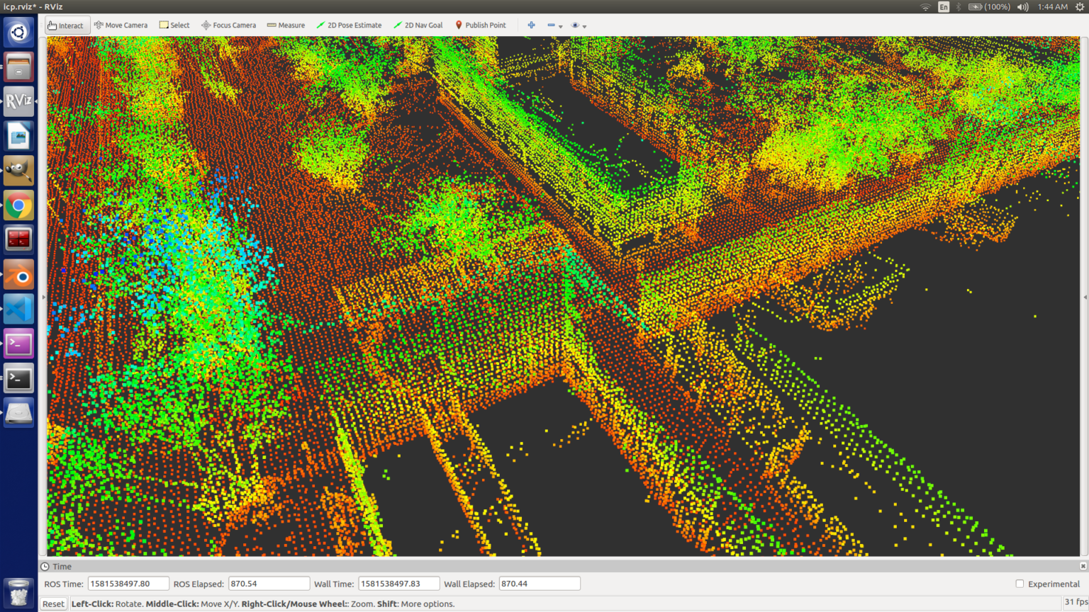
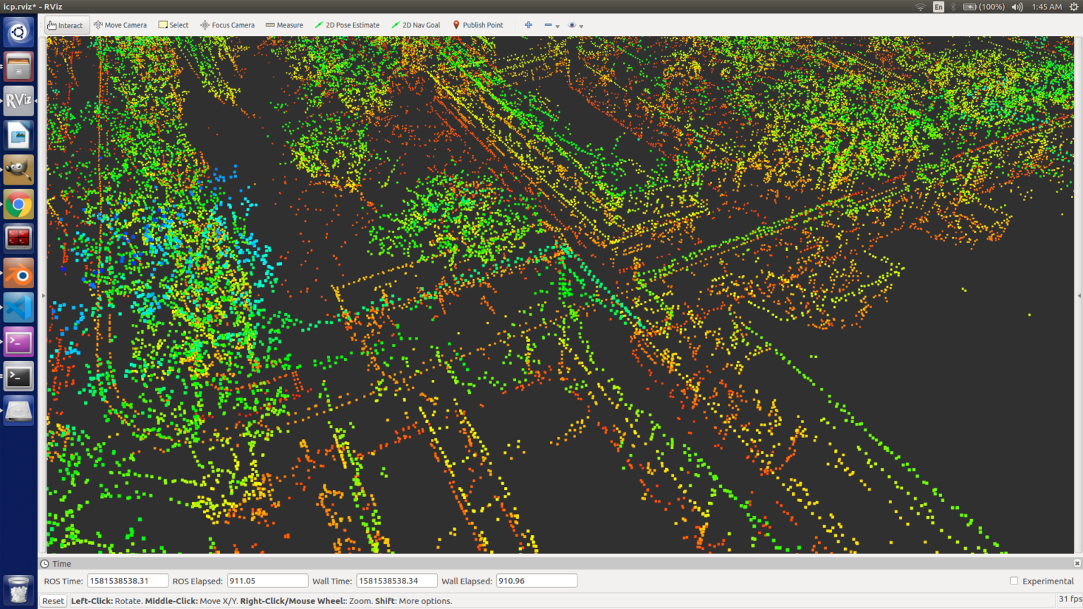
Edge Extraction on Unorganised 3D-Point Cloud
Problem: ICP tends to stuck in local minima, in unfiltered point cloud. Reducing point cloud density is also not of any help as it looses information, therefore essential features needs to be filtered out before using ICP based methods to localize the Autonomous Ground Vehicle in Mapped Environment. The 3D Point Cloud obtained by LIDAR mapping using LOAM package, is Unorganized Point Cloud, so, the existing PCL functions can’t be implemented directly. Thus, for Edge extraction from unorganized point cloud we have implemented the paper “Edge and Corner Detection for Unorganized 3D Point Clouds with Application to Robotic Welding” [https://arxiv.org/abs/1809.10468]. Following are the results from the same.
*Output is not clearly visible. One may download the images to observe better, or drop me a mail if interested.
Input Point Cloud [KITTI Data-set]
Extracted Edge Point Cloud
Removed Point Cloud
Input Point Cloud - IIT Kharagpur Campus
Edge Extracted Point Cloud - Campus
Input Point Cloud - IIT KGP - Department Road
Edge Extracted Point Cloud - Department Road
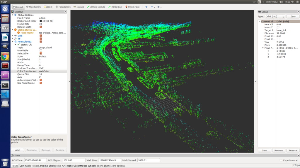
Neighbor Grid Map Import (Saves Computation and Memory)
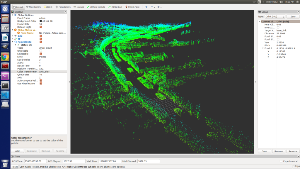
Localization on a pre-mapped environment, importing only the neighbor grid of the map to save computational complexity and make it real-time. 3D Point Cloud is divided into grids and using approximate localization information only neighbor grids are imported. This saves memory and computation and removes map size constraints. This allows us to map the entire city or more, like a set from a smaller resolution, the vehicle can download local area grids from the cloud.
KITTI Dataset [Issue: No Wheel Odometry data] [This causes major drift when vehicle takes the turn]
Red Frame is ICP Correction and Purple Frame is Inertial data based Localisation.
Work Under Progress! The pipeline is ready and being tested in different situations in our self-created dataset. More results will be posted soon!
Removing Wheel Odometry dependency
Wheel odometry, although extremely computationally light, is a very innacurate way to perform localisation as it suffers from significant drift errors. To mitigate this problem, one must use a high frequency LiDAR odometry setup. For achieving high frequencies, the odometry calculation must be fairly lightweight.
Point Correspondence generation
Although the LiDAR outputs and unstructured pointcloud, we can introduce structure based on the workings of the LiDAR. The Idea is that structure in pointclouds will help make better guesses about the correspondences. The LiDAR data is mapped to a range image: an image with (height x width) as (number of lasers x number of points in a revolution per laser) and unwrapped, similar to unwrapping a cylinder to a rectangular piece of paper.
The ground plane is then extracted from the range image and corner and planar features are found. These features are then matched between the two scans based on their segmentation data.
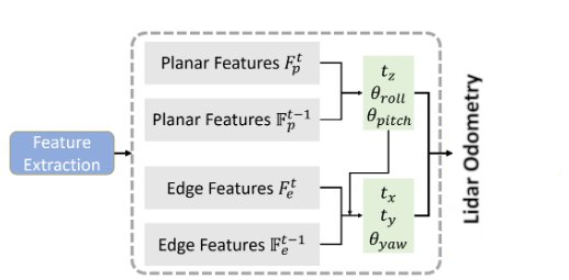
Two Step Pose calculation
Using Levenberg Marquardt Optimisation, we can find the pose of a LiDAR scan relative to another. To make it more accurate, the optimisation takes place in two steps:
Matching the corner features and finding the optimised pose
Matching the planar features of the grouind and finding the optimised pose
Finding the optimised pose in two steps is done becuase corner features (which will mostly be vertical corners) will be very good for finding the 2D movement of the vehicle, as they will give the most accuracy for movement in X and Y directions, as well as provide good yaw estimation, while the plane features (ground) will be more accurate in the movement in Z direction as well as provide good roll and pitch estimation.
So each optimisation provides accuracy in 3 degrees of freedom. These values are calculated and merge into one transform which, when accumulated over time, provides the LiDAR odometry.
Source: LeGO-LOAM: Lightweight and Ground-Optimized Lidar Odometry and Mapping on Variable Terrain – Tixiao Shan and Brendan Englot
The same optimisation technique was used to perform the localisation as well. Here are some of the results:
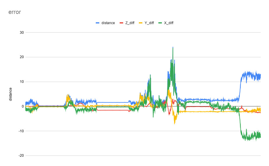
LeGO LOAM performance with CARLA
LeGO LOAM mapping error wrt Ground truth Pose
LiDAR Odometry drift correction by Scan Matching with Prior Map
To be Added:
How to Setup and Run this Package in CARLA
Comparison with other algorithms and pipeline on different computation platform
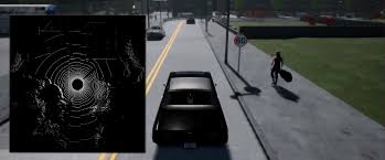
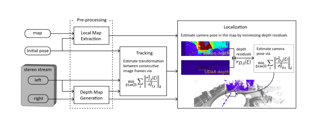
Stereo/RGB-D Camera based Localisation in LIDAR Pointcloud mapped environment
Reference: Stereo Camera Localistion in 3D LiDAR Map [IROS2018] – [LINK]
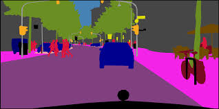
Using Semantic information for Dynamic Foreground elimination to improve accuracy
Updates!
Team Credits: Shreyansh, Siddharth, Radhika, Sombit, Rishabh. Acknowledgment: Prof. Debashish Chakravarty, AGV Research Group, M.N.F.I.C. , IIT Kharagpur